Introduction
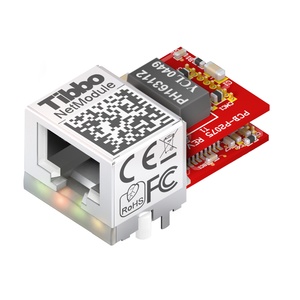
The EM1206 is a miniature BASIC-programmable embedded module. This device is a member of the x20x family of embedded modules and takes full advantage of unique mechanical concept of x20x devices. The module can be used with any suitable jack and magnetics, or with our patent-pending RJ203 jack/magnetics module. The combined PCB footprint of the EM1206 and RJ203 is only 34.5x19mm.
The module's hardware mix, which includes 100Base/T Ethernet, four serial ports, flash disk, EEPROM, and RTC, has been carefully tailored to address the typical needs of network-enabled control applications. This makes the EM1206 especially suitable for "connected" edge products such as sensors, network-enabled card readers, actuators, and other lightweight devices.
The EM1206 is fully supported by TIDE software and a dedicated EM1206 platform that covers all hardware facilities of the module (see "TIDE and Tibbo BASIC Manual"). For convenient testing and evaluation Tibbo offers the EM1206EV evaluation board. The EM1206 can also support Wi-Fi communications (this requires GA1000 add-on board), as well as external LCD, keypad, and buzzer.
Hardware features
•Based on a high-performance purpose-built 88-MHz T1000 ASIC.
•10/100BaseT auto-MDIX Ethernet port (automatic detection of "straight" and "cross" cables). Standard Ethernet magnetics are NOT integrated into the module:
- Connect any suitable external jack and magnetics; or
- Combine the EM1206 with Tibbo's patent-pending RJ203 module to achieve minimal PCB footprint.
•Optional Wi-Fi interface (requires GA1000 add-on module to be connected).
•Four high-speed serial ports (CMOS-level):
- Baudrates of up to 921,600bps;
- None/even/odd/mark/space parity modes;
- 7/8 bits/character modes;
- Full-duplex mode with optional flow control;
- Half-duplex mode with direction control;
- Encoding and decoding of Wiegand and clock/data streams.
•512K or 1024KB flash memory for firmware, application, and data storage.
•2KB EEPROM for data storage.
•RTC with dedicated backup power input.
•Up to 17 general-purpose I/O lines. Among them:
- 8 interrupt lines;
- Serial port lines;
- 16 lines that are combined into two 8-bit ports;
- Square wave output (6Hz - 22'1184MHz), which can be used to control an external buzzer.
•Supports external LCD and keypad.
•Control lines for two external status LEDs.
•Four LEDs onboard:
- Green and red status LEDs;
- Green and yellow Ethernet status LEDs.
•Software-controlled onboard PLL to select the clock frequency of the device: 11.0592MHz with PLL off, 88.4736MHz with PLL on.
•Reliable power-on/ brown-out reset circuit; no additional external reset circuitry required. Master reset input also provided.
•Power: 230mA @ 3.3V (100BaseT mode, PLL on).
•Dimensions: 33.2x18.1x5.5mm.
•Firmware and Tibbo BASIC application are upgradeable through the serial port or network.
•Tibbo BASIC application can be debugged through the network and no additional debugging hardware, such as in-circuit emulator, is required.
Programming features
•Variable Types: Byte, char, integer (word), short, dword, long, real, string, plus user-defined arrays and structures.
•Function Groups: string functions (27 in total!), date/time conversion functions (8), encryption/hash calculation functions (AES128, RC4, MD5, SHA-1), and more.
•Platform objects:
- Sock — socket communications (up to 16 UDP, TCP, and HTTP sessions);
- Net — controls the Ethernet port;
- Wln — handles the Wi-Fi interface (requires GA1000 add-on module);
- Ssi — implements up to four serial synchronous interface (SSI) channels, supports SPI, I2C, clock/data, etc.;
- Ser — in charge of serial ports (UART, Wiegand, and clock/data modes);
- Io — handles I/O lines, ports, and interrupts;
- Kp — scans keypads of matrix and "binary" types (keypad must be connected externally);
- Rtc — keeps track of date and time;
- Fd — manages flash memory file system and direct sector access;
- Stor — provides access to the EEPROM;
- Romfile — facilitates access to resource files (fixed data);
- Pppoe — provides access to the Internet over an ADSL modem;
- Ppp — provides access to the Internet over a serial modem (GPRS, POTS, etc.);
- Pat — "plays" patterns on up to five LED pairs (two LEDs onboard, additional LEDs must be connected externally);
- Beep — generates buzzer patterns (buzzer must be connected externally);
- Button — monitors MD line;
- Sys — in charge of general device functionality.


